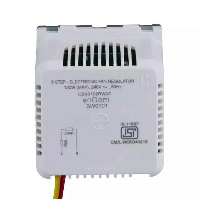
Ceiling fans are a common feature in homes, providing a cost-effective way to cool down spaces. However, controlling their speed efficiently and conveniently is crucial for comfort and energy savings. A 5-step fan regulator circuit offers a straightforward yet effective way to adjust the fan speed in discrete steps, ensuring the right airflow at any given moment. This guide walks you through building a 5-step fan regulator circuit, covering the necessary components, the circuit design, and the assembly process.
Understanding the 5-Step Fan Regulator Circuit
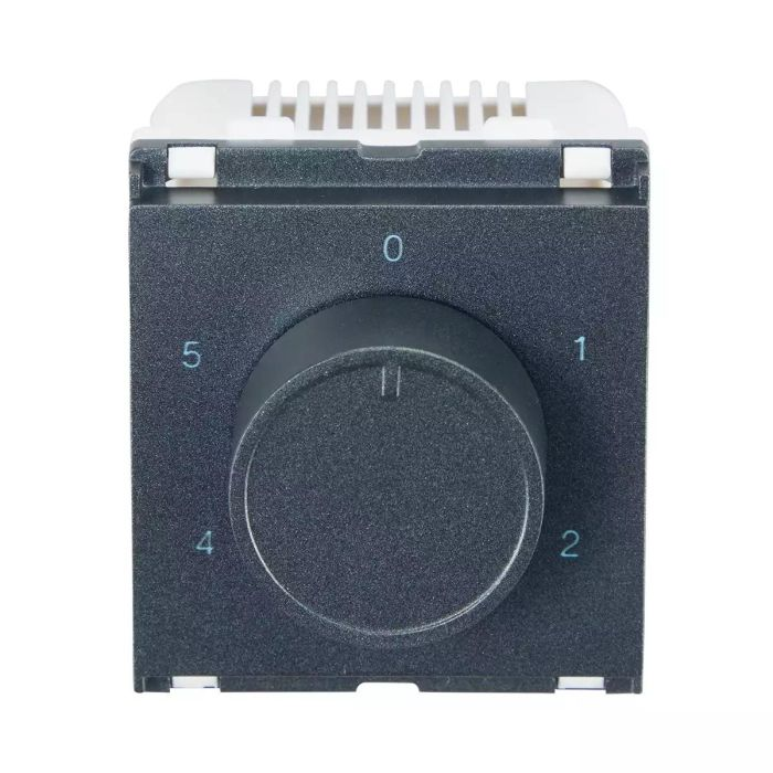
A 5-step fan regulator circuit allows you to set the fan speed at five different levels. This is achieved using a combination of resistors, capacitors, and a switch that toggles between these components to adjust the voltage supplied to the fan. The result is a smooth transition between speed settings, enhancing user comfort and fan efficiency.
Components Needed
To build a 5-step fan regulator circuit, you’ll need the following components:
Resistors: Different resistance values to create various speed steps.
Capacitors: Used to smooth out voltage fluctuations and ensure steady fan operation.
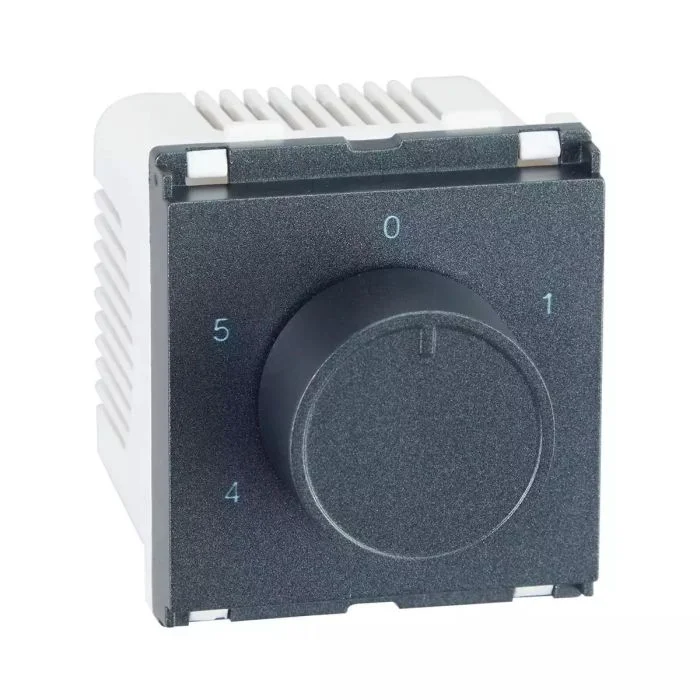
Rotary Switch: A 5-position switch to select the desired speed setting.
Diodes: To protect the circuit from potential voltage spikes.
Transistors: To amplify the current and drive the fan motor.
Printed Circuit Board (PCB): To mount and connect the components.
Wires and Connectors: For connections between components and the power supply.
Soldering Kit: For assembling the components on the PCB.
Step-by-Step Assembly
Step 1: Design the Circuit Schematic
Begin by designing the circuit schematic. The basic idea is to create a voltage divider network using resistors and capacitors. The rotary switch will be used to select different points in the network, thereby providing different voltages to the fan motor.
Resistors: Choose resistors with values that will give you distinct speed steps. For example, you might select 1kΩ, 2kΩ, 3kΩ, 4kΩ, and 5kΩ resistors.
Capacitors: Use capacitors to smooth the voltage. Common values like 0.1µF or 0.01µF are typically used.
Transistors and Diodes: Incorporate transistors to handle the current load and diodes to protect against reverse voltage.
Step 2: Prepare the PCB
Once your schematic is ready, transfer the design onto a PCB. You can either design your own PCB layout using software like Eagle or KiCad or purchase a pre-made PCB designed for fan regulators. Ensure that the PCB has enough space to accommodate all components and traces for the connections.
Step 3: Mount the Components
Start by mounting the resistors and capacitors onto the PCB according to your schematic. Ensure that the components are placed correctly and that the values match your design.
Insert Resistors: Place the resistors in their designated spots. Solder them in place, making sure the connections are secure.
Insert Capacitors: Similarly, place the capacitors on the PCB and solder them in place. Ensure correct polarity for electrolytic capacitors.
Mount Transistors and Diodes: Insert the transistors and diodes, ensuring correct orientation. Solder them securely.
Step 4: Connect the Rotary Switch
The rotary switch will be used to select between the different speed steps. Connect the common terminal of the rotary switch to the input of the fan motor. Then, connect each of the other terminals to the corresponding points in the resistor network.
- Wire the Switch: Use wires to connect the switch terminals to the appropriate points on the PCB.
- Solder Connections: Secure the wires with solder, ensuring solid electrical connections.
Step 5: Final Assembly and Testing
Once all components are mounted and connections are made, it’s time to test the circuit.
Inspect Connections: Double-check all solder joints and connections for any potential shorts or loose connections.
Connect the Power Supply: Carefully connect the power supply to the input of the circuit. Ensure the voltage and current ratings are appropriate for your fan motor.
Test the Circuit: Turn on the power and use the rotary switch to test each speed setting. Verify that the fan operates at different speeds corresponding to the switch positions.
Troubleshooting Tips
- Check Solder Joints: If the circuit does not work, inspect all solder joints for cold solder joints or bridges.
- Verify Component Values: Ensure all components are of the correct values as per the design schematic.
- Test Continuity: Use a multimeter to check the continuity of connections and ensure there are no open circuits.
- Check Power Supply: Ensure the power supply is delivering the correct voltage and current.
Conclusion
Building a 5-step fan regulator circuit is a rewarding project that combines practical electronics with tangible benefits in everyday life. By following this step-by-step guide, you can create a functional and reliable fan speed controller that enhances comfort and efficiency in your home. Whether you’re a hobbyist or a budding electronics enthusiast, this project provides a great opportunity to hone your skills and contribute to a more energy-efficient environment.